Mechanical drives are frequently used in machineries to transmit motion, torque and power from one place to another. Along with transmission of power, such drives can also change direction of rotation, speed and torque. Belt drive, chain drive, rope drive, and gear drive are four major mechanical drives; while, other elements such as shaft, clutch, brake, etc. assist in power transmission. They can transmit power either by means of friction (for example belt and rope drives) or by means of engagement (for example gear and chain drives).
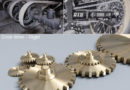
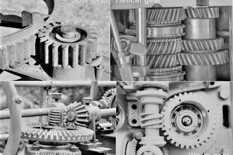
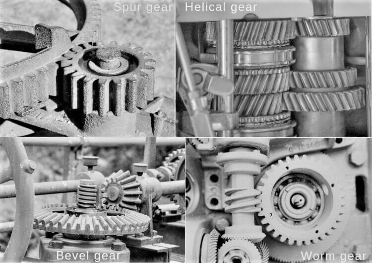
Gear drive is preferably suitable for heavy power transmission over short distance. There are four basis types of gears, namely spur gear, helical gear, bevel gear and worm gear—each of them has different features and provides unique advantages over others. Differences between these four types of gear based on various factors are explained below.
1. Orientation of gear teeth
Gear drive is one engagement type mechanical drive, which indicates motion and power are transmitted directly from driver shaft to one or more driven shafts by means of successive engagement and disengagement of teeth. Different types of gear have different tooth arrangement. During manufacturing of gear, teeth are cut on a cylindrical blank by precisely maintaining several features, one such feature is orientation of teeth with respect to gear axis. Tooth for four types of gear are provided below.
Spur gear— Teeth are straight and parallel to the axis of the gear.
Helical gear— Teeth are neither straight nor parallel to the axis of the gear. They are cut in the form of helix on pitch cylinder; so they are inclined at helix angle with the gear axis; however, never coincide.
Bevel gear— Teeth are straight but not parallel to the gear axis; however, teeth are orientated along the gear axis (in case of straight teeth bevel gears). An extended teeth profile will coincide with gear axis.
Worm gear— Here worm and worm wheel have different teeth profile. Worm is similar to threaded screw (a cylindrical shaft on which threads are cut maintaining constant pitch); whereas, worm wheel has teeth similar to spur gear (straight and parallel to the gear axis).
2. Orientation of driven and driven shaft
Power transmission either between two parallel shafts or between two intersecting shafts or between two perpendicular non-intersecting shafts may be desired in various cases. A particular type of gear is specifically suitable for any one arrangement between driven and driven shaft. For example, spur gear or helical gear are suitable when driver and driven shafts are parallel to each other. Suitability of four types of gear based on relative orientation of driver and driven shafts are discussed below.
Spur gear— It is used to transmit motion and power between two parallel shafts.
Helical gear— It is used to transmit motion and power between two parallel shafts. Crossed helical gears can be employed for non-parallel shafts (usually perpendicular); however, are rarely used.
Bevel gear— It is used to transmit motion and power between two intersecting shafts (not necessarily be perpendicular).
Worm gear— It is used to transmit motion and power between two non-intersecting shafts, which are usually perpendicular to each other.
3. Radial and thrust force on bearings
Mating of two gears imposes force on bearings. These bearings provide support to the driver and driven shafts and ensure correct position. They take up the forces that are acting on the shaft and subsequently transmit them to the ground via frame or casing. A suitable bearing is selected based on numerous factors, notably type and magnitude of force acting on it and rotational speed. Gear drive can impose radial force (acts radially towards centre from the mating point) and thrust force (acts along gear axis).
Spur gear— Since the teeth are parallel to the gear axis, it imposes only radial force to the bearings. No axial thrust force is produced here. However, gear teeth are subjected to a tangential force.
Helical gear— Since the teeth are inclined at helical angle to the gear axis, it imposes both radial force and axial thrust force on the bearings. However, double helical gear is free from thrust force. Tangential force acts on the gear teeth as usual.
Bevel gear— It also produces both radial force and axial thrust force. Additionally tangential force acts on the gear tooth.
Worm gear— Even though the teeth of the worm wheel are straight and parallel to the gear axis (similar to spur gear), both worm and worm wheel impose radial force and thrust force on the bearings. Tangential force acts on the teeth as usual. It is worth mentioning that friction force is significant in worm gear drive because of sliding contact between teeth (unlike rolling contact in other gear drives). Friction force changes radial force and thrust force substantially.
4. Engagement of gear teeth
Since gear is an engagement drive, so teeth of two mating gear successively mesh in a particular fashion. This meshing style has great impact on overall performance of gear drive. It can influence a number of factors including force, vibration, noise, heat generation, tooth wear, service life, and efficiency. Meshing style primarily depends on the orientation of teeth with respect to gear axis, as discussed below for each of the four basic gear types.
Spur gear— Teeth of two mating spur gears, having straight tooth parallel to the gear axis and mounted on parallel shafts, come in sudden contact over the entire face width. Contact between two meshing teeth is always a straight line of length equals to gear teeth width. Sudden contact imposes impact or shock load on teeth.
Helical gear— Here contact between teeth of two mating gears occurs gradually. Initially engagement starts with a point and gradually it becomes a line and thereafter it starts disengaging in reverse way. A gradual load acts on teeth.
Bevel gear— Based on gear teeth type, engagement condition and load varies. In case of straight teeth bevel gear (most common) the mating condition is similar to spur gear (i.e., sudden contact of full length); whereas, in case of spiral teeth bevel gear, mating scenario is similar to helical gear (i.e., gradual contact that starts with a point).
Worm gear— Here teeth of the worm wheel comes in contact with the worm (threaded screw). Although the contact is a line contact (higher pair), the line slides over the surface (instead of rolling as in other types of gear).
5. Power transmission capacity
Gears are used to transmit motion, torque and mechanical power from one place to another and also and alter the same as per requirement. Power transmission capacity of a gear primarily relies on gear size, gear tooth dimensions, number of tooth in contact at a time and gear material. Different types of gears have varying level of capability, as discussed below.
Spur gear— It can be employed for a wide range of power transmission requirements, typically from few watt (for example, watch or toy) to 500 kW (for example, power plant). Size of the gear also varies accordingly.
Helical gear— It can also transmit similar power as spur gear; however, it is preferred over spur gear for high speed applications. Double helical gears and herringbone gears can be used for much higher power transmission range, usually up to 1MW.
Bevel gear— Straight teeth bevel gear can be used for power transmission in the order of 300kW. Spiral bevel gears can, however, transmit more power because of increased contact ratio.
Worm gear— It has very limited power transmission capacity, usually up to 100kW.
6. Vibration and noise
In belt, chain and rope drives, an intermediate flexible element (such as belt, chain or rope) exists in between pulleys or sprockets of driver and driven shafts. This flexible element absorbs vibration arises in driven shaft and thereby protects the prime mover (such as an electric motor, the driver element). No such intermediate flexible element exist in gear drive and thus vibration is transmitted from driven shaft to driver shaft, which is very harmful for prime mover when allowable limit is exceeded. On the basis of how the teeth are mating, different gear drives tends to generate different levels of vibration and noise, as discussed below.
Spur gear— Due to sudden contact between mating teeth, sufficient vibration and noise generate in spur gear arrangement. Moreover, vibration level increases with speed and thus this type of gear is not suitable for high speed applications.
Helical gear— Here teeth of two mating gears gradually come in contact. No impact force exist here. Accordingly, generated vibration and noise levels are comparatively lower.
Bevel gear— Based on the type of teeth, bevel gears may produce similar effects as discussed above. Straight teeth bevel gears will produce effects similar to spur gears (i.e., significant vibration and noise); while, spiral teeth bevel gears will produce effects similar to helical gear (i.e., reduced vibration and noise).
Worm gear— Operation of worm gear is usually smooth and silent as it is used in low speed and low power applications.
7. Achievable velocity reduction
In usual cases, the prime mover (like electric motor or hydraulic turbine) rotates at comparatively higher speed than it is desired in machinery. This requires a reduction in rotational speed between the driver shaft and driven shaft, which can be easily achieved by utilizing different size gears. However, each type of gear arrangement is preferred for a range in speed reduction, as given below. It is worth mentioning that higher reduction can also be achieved by utilizing multi-stage gears.
Spur gear— Spur gears are not suitable for higher speed reduction. It can provide velocity ratio ranging from 1:1 to 4:1.
Helical gear— It can provide little higher reduction as compared to spur gear. It can be applied for velocity ratio in the order of 1:1 to 6:1. However, up to 9:1 speed reduction can also be achieved in single stage for low speed applications if sufficient space is available (higher speed reduction requires larger driver gear).
Bevel gear— It is specifically suitable for 1:1 speed reduction. In certain occasions, it can be applied up to 3:1 reduction.
Worm gear— The biggest advantage of worm gear is its capability to provide steep speed reduction. It can be employed to achieve speed reduction ranging from 15:1 to 60:1; however, a single pair of worm gear can also provide speed reduction up to 100:1.
Scientific comparison among spur gear, helical gear, bevel gear and worm gear is presented in this article. The author also suggests you to go through the following references for better understanding of the topic.
- Design of Machine Elements by V. B. Bhandari (Fourth edition; McGraw Hill Education).
- Machine Design by R. L. Norton (Fifth edition; Pearson Education).
- A Textbook of Machine Design by R. S. Khurmi and J. K. Gupta (S. Chand; 2014).