Machines require a continuous source of power to perform certain task. Majority of industrial machines are driven by mechanical power, which comes in the form of rotational torque. A prime mover is used to generate mechanical energy converting other form of energy; for example an electric motor converts electric energy into mechanical energy. Mechanical power transmission system is used to transmit power from such prime movers to the intended locations of the machine unit. It basically includes four drives; however, takes help of other mechanical elements for uninterrupted power transmission. Gear drive, belt drive, chain drive and rope drive are four mechanical drives that can transmit motion, torque and power from driver shaft to driven shaft. Each of these four drives has different features and thus can offer specific benefits over others.
A gear drive is one engagement type rigid mechanical drive that is suitable for small distance power transmission. It can transmit heavy power without any slip (positive drive). Based on the relative orientation of driver and driven shafts and teeth profile, gear drive can be classified into four groups—spur gear, helical gear, bevel gear and worm gear. Spur gear is the simplest type of gear having straight teeth parallel to the gear axis and can transmit power between parallel shafts only. Although helical gear is also used for parallel shafts, teeth are not parallel to the gear axis. Here teeth are cut in helical form on the gear blank maintaining same helix angle. Bevel gear may have straight or spiral teeth and is used for intersecting shafts; while, worm gear is used for perpendicular but non-intersecting shafts.
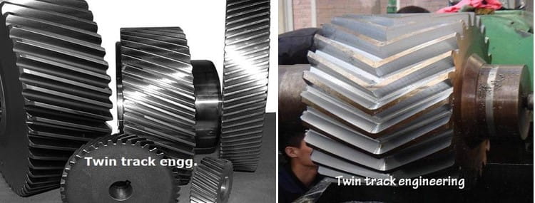
Although helical gears offer certain benefits over spur gear, it imposes axial thrust load on the bearing. This thrust load is detrimental and limits the power transmission capability. Moreover it requires costly and bulky bearings to withstand under radial and axial loadings. However, this thrust load can be eliminated by utilizing herringbone or double helical gear. In herringbone gear, teeth are cut in two halves of the gear blank maintaining same module, number of teeth and helix angle but opposite hand of helix. Thus thrust force produces by each half of the herringbone gear is equal and opposite and thus eliminates each other. Moreover, it can transmit comparatively higher power without much problem. Various differences between helical gear and herringbone gear are given below in table format.
Table: Difference between helical gear and herringbone gear
| Helical Gear | Herringbone Gear |
|---|---|
| Teeth of the helical gear are cut in the form of a helix (either left hand or right hand helix) on the cylindrical gear blank. | Identical teeth are cut in two halves of the gear blank maintaining same module, number of teeth and helix angle but opposite hand of helix. |
| A pair of mating helical gears produces significant radial thrust force. | Thrust force produces by each half of the gear is equal and opposite in direction; and thus they cancel out each other. |
| Radial thrust force limits the helix angle to a maximum of about 25°. | Absence of thrust force gives the provision to use higher helix angle (up to about 45°). |
| Bearings that can handle both axial load and thrust load are required to use with helical gear. | Since thrust force does not exist, so bearings that can handle heavy radial load can be used with herringbone gear. |
| Power transmission capability of helical gear is comparatively small. | It can transmit very high mechanical power or torque. |
| Design and manufacturing of helical gear is easier and thus it is cheap. | Herringbone gear is expensive because of complicated design and manufacturing. |
Teeth profile: Teeth of the helical gear are cut in the form of helix on the pitch cylinder. A particular helical gear consists of either left hand helix teeth or right hand helix teeth. At the time of engagement, a helical gear with left hand helix can only mate with a helical gear with right hand helix. On the other hand, a herringbone gear consists of both hands of helix in a single gear unit. Each herringbone gear has two distinct halves—one halve must have left hand helix teeth and the other halve should have right hand helix teeth. Other features such as pitch circle diameter, module, number of teeth, helix angle and width or thickness will be same in both the halves; the only difference is their hand of helix.
Thrust force: Helical gear offers many benefits over spur gear, such as gradual loading on teeth, less vibration, more loading capacity, higher service life, etc. Main drawback is the thrust load. Since teeth of spur gear ate straight and parallel to the gear axis, so a pair of mating spur gears induces only radial load. Due to helical form of teeth, a pair of mating helical gears induces both radial load and axial load. Thus stronger bearings are required to sustain both types of load simultaneously. Herringbone gear can offer similar benefits as the helical gear and at the same time eliminates the thrust force. Here thrust force produces by each halve is equal and opposite (because of opposite hand of helix) and thus the resultant thrust force becomes zero. So a pair of mating herringbone gears induces no axial thrust force on the bearings (only radial force exists).
Helix angle: Thrust force increases with helix angle of the teeth; however, a higher helix angle can significantly reduce vibration and tooth wear and increase load carrying capacity. This thrust force limits the maximum helix angle in case of helical gear. Typically it is kept in between 20 – 25°. However, absence of thrust force in herringbone gear facilities use of higher helix angle, even up to 45°.
Bearings for mounting the shafts: Driver and driven shafts are mounted at both ends using appropriate bearings. Apart from supporting the shafts and maintaining accurate position, bearings also talk away the vibration and load, and subsequently transmit them to the ground via frame. Typically rolling contact bearings are employed in gear units, unless the rotational speed is very high. There are various types of rolling contact bearings, some of them are suitable for radial load only, some are suitable for axial load only and few can handle radial and thrust load. For example, deep groove ball bearings, angular contact bearings and taper roller bearings can handle both radial load and thrust load. Thus these bearings can be employed for helical gear unit. On the other hand, cylindrical roller bearings can handle heavy radial load and thus can be utilized with herringbone gear unit.
Power transmission capacity: Basic function of every mechanical drive is to transmit mechanical power from driver shaft to driven shaft. Different drives offer varying level of transmission capacity based on size, material and other features. Although transmission capacity of helical gear is comparatively higher than that of similar spur gear, it is generally not used for heavy duty applications. The thrust load and availability of bearings impose the limit in heavy duty applications. Herringbone gear and double helical gears are preferred choice for such areas. For example, herringbone planetary gear train (HPGT) can be observed in heavy machineries like coal cutter, aerospace engine, wind turbine, etc.
Gear fabrication: Cutting helical teeth on the cylindrical gear blank is not difficult; however, problem arises when clearance does not exist at the end of teeth. Like spur gear, helical gear teeth can also be cut by pinion-type gear shaping cutter. Hobbing can also be used for cutting helical gears. But in herringbone gear, no relief gap exist between left and right halves. Thus cutting teeth at this junction is quite complicated as there exists a risk of overstepping to the other halve. It requires specialized hobbing cutter having a grove matching with the herringbone gear. High degree of locational and angular alignment are also required to maintain.
Scientific comparison among helical gear and herringbone gear is presented in this article. The author also suggests you to go through the following references for better understanding of the topic.
- Design of Machine Elements by V. B. Bhandari (Fourth edition; McGraw Hill Education).
- Machine Design by R. L. Norton (Fifth edition; Pearson Education).
- A Textbook of Machine Design by R. S. Khurmi and J. K. Gupta (S. Chand; 2014).