Mechanical drives are used to transmit motion, torque and power from a driver shaft to driven shaft. The driver shaft, in majority of the cases, is a part of prime mover (such as electric motor, hydraulic turbine, steam turbine, etc.); while, the driven shaft is a part of the machine unit. There exist four basic mechanical drives, namely gear drive, belt drive, chain drive and rope drive. A gear drive is one engagement type rigid drive where motion and power are transmitted by means of successive engagement and disengagement of teeth of two mating gears. It is inherently free from slip and this it provides constant velocity ratio (positive drive). It can be used for light duty applications (such as toys, watches, etc.) as well as for heavy duty applications (such as gear box of machinery, marine drive, etc.).
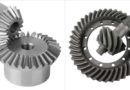
Driver and driven shafts may have three mutual orientations, namely (i) parallel shafts, (ii) intersecting shafts and (iii) non-parallel non-intersecting shafts. There exist four basic types of gears and a suitable gear should be selected based on the mutual orientation of the driver and driven shafts. Spur gear and helical gear are applicable for parallel shafts. Bevel gear can be applied for two intersecting shafts, which may not necessarily be perpendicular. Worm gear arrangement is used for the third category (non-parallel non-intersecting shafts). Unlike spur gears that have straight teeth parallel to the gear axis, helical gears have teeth in helical form that are cut on the pitch cylinder. Although helical gears are commonly used for parallel shafts like spur gears, it can also be used for perpendicular but non-intersecting shafts.
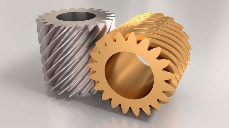
Accordingly there are two types of helical gears—parallel and crossed. Parallel helical gears, the common one, is used to for power transmission between parallel shafts. Two mating parallel helical gears should have same module, same pressure angle but opposite hand of helix. They offer vibration-free and quiet operation and can transmit heavy load. On the other hand, crossed helical gears are used for non-intersecting but perpendicular shafts. Two mating crossed helical gears (also called screw gears) should have same module, same pressure angle and either same or opposite hand of helix. This type of gear has application similar to worm gear; however, worm gear is preferred for steep speed reduction (1:15 to 1:100), whereas crossed helical gears cannot provide speed reduction beyond 1:2. Various differences between parallel helical gear and crossed helical gear are given below in table format.
Table: Differences between parallel helical gear and crossed helical gear
| Parallel Helical Gear | Crossed Helical Gear |
|---|---|
| Parallel helical gears can transmit motion and power between parallel shafts only. | Crossed helical gears can transmit motion and power between perpendicular but not-intersecting shafts. |
| Two mating gears must be mounted on two parallel shafts. | Two mating gears are mounted on two perpendicular but non-intersecting shafts. |
| Two mating gears should have same helix angle but opposite hand of helix. | Two mating gears may have different helix angles. They may have either same or opposite hand of helix. |
| Engagement between two teeth starts with a point contact but gradually becomes a line contact. | Two meshing teeth always have point contact. |
| Power transmission capacity of parallel helical gear is higher due to broader contact. | Crossed helical gear has lower power transmission capacity due to point contact. |
| It has wide area of application ranging from small equipment to large industrial field including gear trains. | It is rarely used in small size instruments. |
Power transmission and orientation of shafts: Except quarter-turn belt, gear drive is only mechanical drive that can be advantageously employed to transmit power and motion at any angle at any plane. Different types of gear are preferred for varying orientations of driver and driven shafts. Similar to spur gears, parallel helical gears can transmit motion and power between parallel shafts only. Therefore they should be mounted on parallel shafts with proper locational and angular alignment. On the other hand, crossed helical gears or screw gears can transmit motion and power between perpendicular shafts and thus they should be mounted on perpendicular but non-intersecting shafts.
Hand of helix: Irrespective of parallel or cross arrangement, two mating helical gears should have same module, same pressure angle and same helix angle. Pitch circle diameter of two mating gears should also touch at a single point. Now, if the mating helical gears have parallel arrangement, then one gear should have right hand helix and other gear should mandatorily have left hand helix. Thus, two mating parallel helical gears must have opposite hand of helix. However, in case of crossed arrangement, one helical gear with right hand helix can mate with another helical gear having either left or right hand helix. Thus, two mating crossed helical gears may have same or opposite hand of helix.
Contact between teeth: Based on the teeth profile and gear orientation, contact between teeth of two mating gears occurs in several fashions. For example, teeth of two spur gears come in sudden contact and their contact length always remains a line of length equals to face width of teeth. Such sudden contact is replaced by gradual contact in helical gear. In case of parallel helical gears, the mating of two teeth initiates with a point and gradually becomes a line and then they disengage as a point. However, in case of crossed helical gears, contact between two teeth always remains a single point. At the beginning of engagement, this point lies at one end of the teeth face and gradually the contact point moves over the face. At disengagement, the contact point lies on the other end of the teeth face.
Power transmission capacity: Basic purpose of every mechanical drive is to transmit power from driver shaft to driven shaft. Being an engagement type rigid drive, gear drive has the maximum transmission capacity among all mechanical drives. However, different types of gear drive offer varying level of power transmission capacity. A pair of parallel helical gears can transmit comparatively higher power as compared to similar size spur gear of same material. Based on the size and material, parallel helical gears can transmit from only few watt to few mega-watt power. On the other hand, crossed helical gears are preferred for small power transmission, usually limited to 100kW.
Areas of application: Due to high power transmission capacity, parallel helical gears are advantageously employed in many fields. It can be successfully employed for low speed as well as high speed applications. Typical areas of application include gear box of machine, automobile, oil mill, marine drive, etc. On the other hand, crossed helical gears are suitable for low speed and low duty applications such as roving machine of textile industry, oil pump of internal combustion engine, etc.
Scientific comparison among parallel helical gear and crossed helical gear is presented in this article. The author also suggests you to go through the following references for better understanding of the topic.
- Design of Machine Elements by V. B. Bhandari (Fourth edition; McGraw Hill Education).
- Machine Design by R. L. Norton (Fifth edition; Pearson Education).
- A Textbook of Machine Design by R. S. Khurmi and J. K. Gupta (S. Chand; 2014).