A machine is composed of mechanisms. These mechanisms provide relative motions that can be utilized to perform certain task with minimal intervention. All these mechanisms essentially require a source of power to perform the intended work. This power source can be human power; however, in 21st century with the fourth industrial revolution (Industry 4.0) in rolling, elimination of human power requirement to drive a machine is one obsolete idea. A machine can be driven smoothly using other forms of power supply, which includes fluid power (hydraulic and pneumatic), electric power, mechanical power, and thermal power. Although, electric power is overwhelmingly used in household and industrial machineries, fluid power is slowly gaining popularity because of certain inherent benefits including easy control and elimination of intermediate mechanical elements.
Mechanical power deals with the motion and torque of a rigid dynamic body. It does not generate power; instead, it retrieves power from a prime mover (either electrical or fluid based) and converts it to mechanical power to directly transmit it to machinery. Prime roles of mechanical power transmission system include—(i) transmitting motion and torque from one place to another, (ii) changing the sense of rotation like clockwise to counter-clockwise or vice versa, (iii) increasing or decreasing the speed or torque, and (iv) to protect the driver from overloading and vibration. Mechanical transmission system employs one or more drives and elements to fulfil such requirements. Four basic mechanical drives are gear drive, belt drive, chain drive and rope drive. Various elements that assist in transmitting mechanical power include shaft, pulley, sprocket, key, brake, clutch, coupling, etc.
Four drives of the mechanical power transmission system can be classified in various ways. One such way is to classify on the basis of presence of intermediate flexible element. In all those drives where driver and driven shafts are connected by an intermediate flexible element are classified as flexible drive. Belt drive, chain drive and rope drive fall under this category as flexible element such as belt, chain and rope exists in between driver and driven shafts. On the other hand, when driver and driven shafts are connected by two rigid bodies, then it is termed as rigid drive. Any intermediate flexible element does not exist here. Gear drive comes under this category. Various differences between flexible drive and rigid drive are given below in table format.
Table: Difference between flexible drive and rigid drive
| Flexible Drive | Rigid Drive |
|---|---|
| In flexible drive, driver and driven shafts are connected by an intermediate flexible element like belt, chain, wire, etc. | In rigid drive, no intermediate flexible element exist between driver and driven shafts. |
| It is suitable for transmitting power and motion over a longer distance. | It is preferred for short distance power and motion transmission. |
| Any vibration in the driven shaft is absorbed by the flexible elements and thus driver shaft remains safe. | In absence of flexible elements, vibration of driven shaft is fully transmitted to driver shaft. |
| With flexible drive, the driver and driven shafts can be rotated either in same or in opposite direction. | With rigid drive, the driver and driven shafts cannot be rotated in same direction without using additional element. |
| It is not reliable for very high torque or power transmission. | It can be safely used for high power transmission requirements. |
| It may not provide constant velocity ratio. | It can provide constant velocity ratio. |
| It is not recommended for large velocity reduction. | It can be safely used for steep velocity reduction. |
| It gives flexibility in location and orientation of driven shaft with respect to driver shaft. | Locational accuracy of driver and driven shafts is very important to get desired performance. |
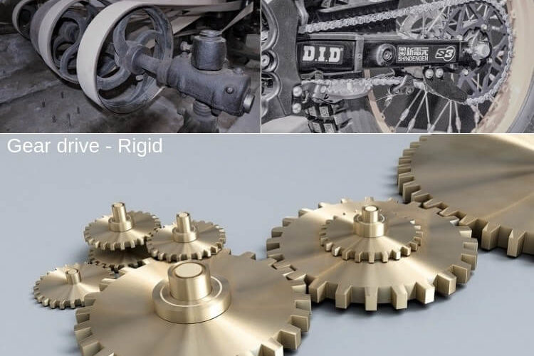
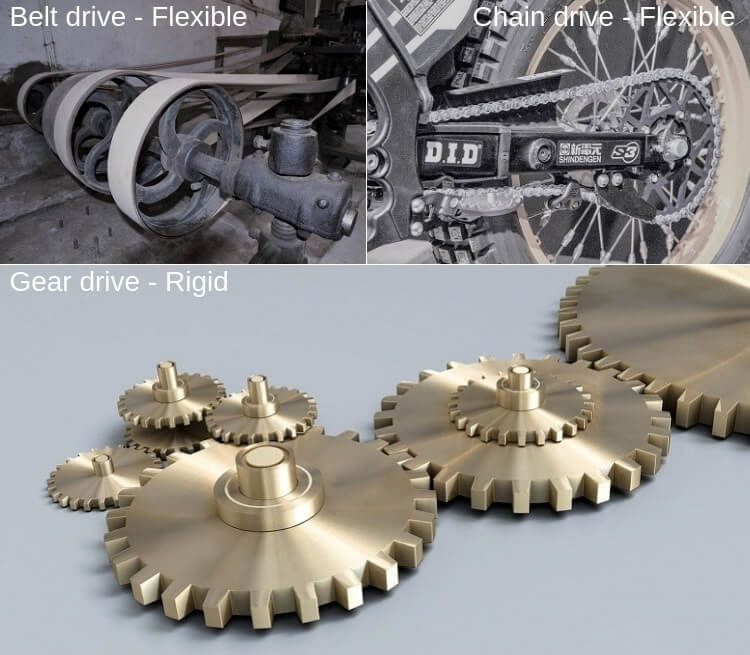
Examples of flexible drive:
|
Examples of rigid drive:
|
Presence of intermediate flexible element: Belt drive consists of two pulleys—one is fixed with driver shaft and other one is fixed with driven shaft. A hinged or endless belt partially circumambulate these two pulleys. Frictional force acting in between pulleys and belt help transmitting power from one shaft to another. This belt is one flexible link as it can easily bent in different directions. Similarly, in case of rope drive, the flexible rope connects the driver and driven pulleys. Although chain drive is not a friction drive (it is one engagement type drive), the chain itself is a flexible element. Therefore, in every flexible drive, an intermediate flexible element exists to connect pulleys or sprockets of the driver and driven shafts. But in case of rigid drive, no such intermediate element exist. Here the shafts are directly attached by means of rigid elements. For example, in gear drive, two gears remain in direct contact and no intermediate linkage is necessary.
Long distance motion transmission: Basic purpose of mechanical drives is to transmit motion, torque and power from prime mover (such as an electric motor) to machinery or equipment. The distance between the driver and driven shafts can vary from a fraction of a meter to as high as 20 meters depending on the shop floor layout, machinery size, etc. Flexible drives are preferred for medium to large distance motion or power transmission as they consists of an intermediate linkage whose length can be varied easily based on the requirement. For example, flat belt drive is suitable if centre distance is more than 3m. On the other hand, rigid drive is a good choice for short distance power transmission. For example, gear drive is suitable up to 1m centre distance. If it is used for large centre distance then either bulk size gears have to be employed or a number of intermediate gears have to be attached, which will unnecessarily increase system weight and power loss.
Capability to absorb vibrations: Vibration is inherent to every industrial machinery. It arises mainly due to unbalanced force and loose, misaligned or worn out parts. Undesired vibration can affect the system in many ways such as quickly loosening the threaded elements, causing inaccuracy in movement, abrading materials at higher rate, creating cracks on welded joints, etc. Although machine base tends to dampen the vibration by transmitting it to the ground, it cannot be eliminated fully. A flexible linkage also has the capability to absorb or dampen vibration without creating noticeable problem on power and motion transmission. So vibration induced in the machinery cannot transfer to the prime mover and vice versa. Thus flexible drives can easily protect the entire system from vibration. But in case of rigid drive, vibration cannot be damped at all because of the absence of any flexible linkage.
Direction of rotation: Belt and rope drives give the flexibility to rotate the driven shaft either in same or in opposite direction without utilizing any additional element. For example, an open belt drive can rotate the driven shaft in same direction as in driver shaft; however, in cross belt drive, their directions of rotation are opposite. With only one driven shaft, chain drive can rotate in same direction only. However, if three or more shafts are required to rotate simultaneously by taking power from one driver shaft, then achieving multi-directional rotation is feasible. On the other hand, gear drive can provide opposite direction of rotation only. In order to get same rotational direction, idle gear is required to employ additionally, which can undesirably increase system weight and power loss.
High torque transmission: Torque or power transmission capacity of belt and rope drives (friction drives) is limited to the friction force or dynamic coefficient of friction between pulleys and belt/rope. In chain drive, strength of pin joints of the chain limits the transmission capacity. Such intermediate linkage is not present in rigid drive. Thus it can transmit comparatively large torque.
Velocity ratio (VR): It is defined as the ratio of rotational speed (not the peripheral velocity) of the driver shaft to the driven shaft. Slip occurs frequently in belt and rope drive and thus they cannot provide a constant velocity ratio. Although slip does not occur in chain drive, the polygonal effect can alter velocity ratio. Thus flexible drives cannot provide constant velocity ratio and thus they are not positive drives. On the other hand, rigid drive is positive drive and thus they can provide constant velocity ratio.
Velocity reduction: Usually prime mover rotates at a higher speed; but the required speed in the driven shaft of the machinery is comparatively low. Reduction of rotational speed is another desired function of the mechanical drives. The pulley, sprocket and gear wheel sizes are chosen in such a way that their peripheral velocity remains same but their rotational speed varies according to desired velocity ratio. However, large velocity reduction is not possible with flexible drives. They are suitable up to 7:1 reduction. However, rigid drives can be employed for steep reduction, even up to 40:1 (using worm gear).
Flexibility in location and orientation: Small amount of angular or locational misalignment cannot create much problem in flexible drives. But rigid drives require precise alignment for smooth performance, low vibration and longer service life. Although misalignment is not tolerable, they can be advantageously employed for non-parallel shafts having proper alignments (for example, bevel gear and worm gear).
Scientific comparison among flexible drive and rigid drive is presented in this article. The author also suggests you to go through the following references for better understanding of the topic.
- Design of Machine Elements by V. B. Bhandari (Fourth edition; McGraw Hill Education).
- Machine Design by R. L. Norton (Fifth edition; Pearson Education).
- A Textbook of Machine Design by R. S. Khurmi and J. K. Gupta (S. Chand; 2014).