Machine can be defined as a cluster of mechanisms that can perform certain task by expanding energy. Such mechanisms are driven by mechanical power, which come in the from of rotational torque. A prime mover (such as electric motor, turbine, etc.) usually supplies mechanical power and it is then transmitted to the machine unit with the help of mechanical drives. There are four mechanical drives, namely gear drive, belt drive, chain drive and rope drive. Gear drive transmit motion and power from driver shaft to driven shaft by means of engagement of teeth. It is one rigid drive due to absence of any intermediate flexible element. It can transmit light to heavy power without any slip (positive drive) basic is preferred for small distance power transmission.
There exist four basic type of gears—spur gear, helical gear, bevel gear and worm gear. Spur and helical gears are used for parallel shafts; however, spur gear has straight teeth parallel to the gear axis; while, helical gear has teeth in helical form that are cut on the pitch cylinder. This helical form of teeth offers certain advantages such as gradual pick up of load on the tooth, less vibration, less noise, less wear, etc. A pair of bevel gear can be applied for transmitting motion and power between intersecting shafts (usually perpendicular); while, worm gear arrangement is applicable for non-parallel and non-intersecting shafts. There are different types of bevel gears, such as straight bevel gear, skew bevel gear, face gear, spiral gear, hypoid gear, crown gear, zerol gear, etc. Each of them has different feature and are suitable for particular type of applications.
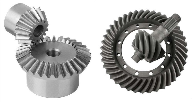
Teeth of the bevel gear can have either straight or spiral profile; however, both are applicable for intersecting shafts only. As the name suggests, in straight teeth bevel gear, teeth are straight like spur gear but are cut along the gear axis maintaining an inclination. Due to sudden contact between teeth of two mating gears, tooth experiences impact load. This results in vibration and noise. Face bevel gear and skew bevel gear also have straight teeth. Spiral teeth helical gears offer similar benefits over straight teeth bevel gears as the helical gears provide over spur gears. Here teeth have a spiral profile and thus gradually come in contact during mating. Thus it offers smooth, vibration-free and quiet operation. However, it exerts high thrust load on the bearings. Hypoid gear also have spiral teeth. Various differences between straight bevel gear and spiral bevel gear are given below in table format.
Table: Differences between straight bevel gear and spiral bevel gear
| Straight Bevel Gear | Spiral Bevel Gear |
|---|---|
| Teeth of this type of gear are straight and are cut along the axis on a cone. | Here the teeth are spiral and are cut in the form of spiral curve on the pitch cone. |
| Two teeth of the mating gears come in sudden contact. The contact is always a line of length equals to face width of teeth. | Teeth of two mating gears gradually come in contact. Engagement starts with a point and gradually becomes a line. |
| Due to sudden contact, teeth are also subjected to impact or shock loading. | Here teeth are subjected to gradual loading. |
| Sudden contact also causes noise. | Its operation is quite. |
| Shock loading induces vibration and thus its operation is not smooth. | Due to gradual building up of load, it produces less vibration and thus the operation is smooth. |
| Designing and manufacturing of straight teeth bevel gear are easier and thus these are cheaper. | Complicated design and manufacturing leads to higher cost for this type of gear. |
| It exerts less thrust force on the bearings that hold the shafts. | It exerts more thrust force on bearings. |
Teeth orientation: Bevel gears may have either straight or spiral teeth. When teeth of a bevel gear are straight but inclined in such a way that they converge into a common apex point, then that gear is called straight bevel gear. Two such gears should be mounted on intersecting shafts only. A variant of straight bevel gear, called skew bevel gear, can be employed for non-parallel and non-intersecting shafts. On the other hand, when teeth are cut in spiral form on the conical gear blank in such a way that spiral curves converge in a single apex point, then it is termed as spiral bevel gear. A pair of mating spiral bevel gears should be mounted on intersecting shafts; alternatively hypoid gear (also has spiral teeth) can be employed for non-parallel and non-intersecting shafts.
Contact scenario: Gear drive is one type of rigid engagement drive that indicates teeth of two mating gears come in direct contact to transmit motion and power from one shaft to another. Irrespective of gear type, teeth that are parallel to gear axis come in sudden contact. This happens in case of spur gears as well as straight bevel gears. Here the contact is always a line of length equals to face width of the teeth. On the other hand, teeth of two mating spiral bevel gears come in contact gradually, as it happens in helical gears. Here engagement initiates with a point and gradually becomes a line and finally disengages as point.
Impact load and its consequences: Due to sudden contact, teeth of the straight bevel gears experience impact or shock loading. It also results in considerable noise and vibration. This vibration sometimes imposes limit on maximum speed of operation and also power transmission capacity. On the other hand, teeth of the spiral bevel gears experience gradual loading, which is far less deleterious. Their operation is thus smooth and quiet, even at high speed.
Cost comparison: Complicated manufacturing leads to high price for spiral bevel gears. For same material, size and tolerance, spiral gears are 1.2 – 1.5 times costly than straight bevel gears. Cost difference increases when gear size is small due to difficulty in manufacturing. High finishing requirement may also lead to broader price difference.
Thrust force: Two mating gears always exert force on the bearings that mount the shafts. Based on teeth orientation, this force can be either radial or axial or both. For example, straight teeth that are parallel to gear axis (as in spur gear) produce only radial load; whereas, helical teeth (as in helical gear) produces both type of force. Straight bevel gears as well as spiral bevel gears produce both radial and thrust load; however, thrust load (axial) in spiral bevel gear is comparatively higher as it induces from two sources.
Scientific comparison among parallel helical gear and crossed helical gear is presented in this article. The author also suggests you to go through the following references for better understanding of the topic.
- Design of Machine Elements by V. B. Bhandari (Fourth edition; McGraw Hill Education).
- Machine Design by R. L. Norton (Fifth edition; Pearson Education).
- A Textbook of Machine Design by R. S. Khurmi and J. K. Gupta (S. Chand; 2014).