Machining or metal cutting is one secondary manufacturing process where excess material is gradually removed from the workpiece in order to impart desired finish, dimension and tolerance. To cater the need of efficiently and economically machining a wide variety of materials in different ways, several relevant processes have emerged over the years. Broadly these processes can be grouped as conventional machining (macro and micro), abrasive finishing and non-traditional machining (NTM). Conventional machining processes are well established and it consists of a large number of operations for generating various features. For example, turning, milling, threading, knurling, facing, drilling, boring, reaming, etc. All these operations are carried out with the aid of a cutting tool that actually removes material from workpiece in the form of chips.
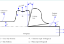
Cutting tool, also called cutter, is a wedge shaped and sharp edged device that compresses a thin layer of workpiece material to shear it off the form of chips during machining. During machining, the machine tool actually holds the cutter and job, and at the same time it imparts desired relative motions (speed, feed, depth of cut). Therefore, cutter is a part and parcel of every conventional machining operation; however, its shape and size may vary depending on the feature to be produced and operation employed. Whatever be the geometry of cutter, it must consists of a sharp cutting edge to swimmingly remove material requiring minimum effort. A cutting edge is basically one straight or curved edge produced by intersection of any two tool point surfaces (rake surface, principal flank surface and auxiliary flank surface). Based on the number of cutting edge present, cutters can be classified as single point cutter and multi point cutter.

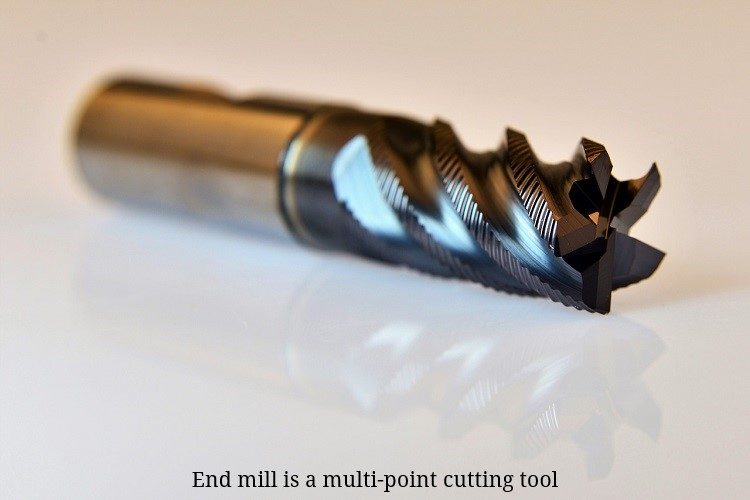
A single point cutter contains only one main cutting edge that can actively participate in material removal action during machining. Thus one cutting edge removes entire volume of material in a single pass. Contrary to this, a multi-point cutter consists of at least two cutting edges and all of them can equally participate in material removal action in a single pass. Thus chip load per cutting edge reduces significantly. Turning, shaping, planning, boring, fly cutting, etc. operations are performed using single point cutter; while, milling, drilling, knurling, reaming, etc. utilize multi-point cutter. A multi-point cutter can contain from two (drill or end-mill) to hundreds of cutting edges (abrasives of grinding wheel). Various differences between single point cutter and multi point cutter are given below in table format.
Table: Differences between single point and multi point cutters
| Single Point Cutter | Multi Point Cutter |
|---|---|
| Single point cutters contain only one main cutting edge that can actively take part in shearing in a single pass during machining. | Multiple point cutters can contain more than one (two to hundreds) cutting edges that can take part in shearing in a single pass. |
| A single cutting edge remains in continuous contact with the workpiece. | Here all cutting edges may or may not remain in continuous contact with the workpiece. |
| Due to continuous contact, rate of rise in tool temperature is high and thus proper precautions must be adopted to keep thermal damages at bay. | Usually cutting edges simultaneously engage and disengage during cutting and thus inherently protects itself from overheating and consequent damages. |
| Entire chip load in a single pass is borne by only one cutting edge. | Entire chip load in a single pass is distributed among all cutting edges. |
| Lower speed, feed and depth of cut is employed to protect cutting tool from unplanned breakage. So MRR and productivity are low. | Higher speed, feed and depth of cut can be employed safely. So MRR and productivity are higher. |
| Unplanned breakage of one cutting edge requires immediate termination of entire process and replacement of cutter. | Breakage of one cutting edge does not possess significant problem and thus operation can be carried out, at least for that pass. |
| Single point cutters are easy to design and fabricate. | Multi-point cutters are comparatively difficult to design and fabricate. |
Following machining operations are carried out using single point cutter:
|
Following machining operations are carried out using single point cutter:
|
Number of cutting edges: As the name suggests, single point cutting tools consist of only one main cutting edge. This edge participates in material removal action throughout the pass during machining. In the next pass, either the same cutting edge can be utilized or it can be replaced with a new sharper one. It is worth noting that such cutters may contain more than one cutting edges at a time on the tool; however, only one will engage during machining (for example consider insert based turning tool that usually contains 3 or 4 cutting edges present on the tool body at a time but only one partakes in cutting). Contrary to this, multi-point cutters contain more than one cutting edges and all (or most of them) actively participate in shearing action in a single pass.
Contact between cutter and workpiece and its consequence: When machining is carried out using single point cutter, only one cutting edge remains in continuous contact with the workpiece. This causes sharp increase of tool temperature and the result is thermal damages of cutter like enhanced rate of wear, plastic deformation, degraded tool life, etc. Thus proper precautions (like smaller speed, feed and depth of cut, application of coolant, insulated coating on cutter, etc.) must be taken to get rid of such damages. On the other hand, in multi-point cutter either all (example drilling, reaming, etc.) or only few engage with workpiece (example hobbing, broaching, etc.). Usually cutters with higher number of edges, remove material by simultaneous engagement and disengagement of cutting edges. This protects the cutter from overheating by allowing sufficient time to dissipate heat during disengagement period. However, intermittent cutting can increase vibration and unbalanced forces.
Chip load: It is axiomatic that during machining the cutter compresses a thin layer of work material and gradually shears if off. So in every instant, cutter movement is restricted by an area of work material, which is expected to be removed. This area of workpiece material just ahead of the cutter at a particular instant is called chip load. Mathematically it can be expressed by the multiplication of feed and depth of cut (s×t) and can be expressed either in terms of per unit time or per revolution. In case of single point cutter, entire chip load is borne by only one cutting edge; while, in multi-point cutter entire chip load is distributed among all cutting edges and thus each edge is subjected to significantly smaller chip load.
Provision for higher speed, feed and depth of cut: With single point cutter, if higher speed, feed and depth of cut are employed then cutting edge will subject to higher chip load and thus tool may fail prematurely by catastrophic breakage. With multi-point cutter, higher speed, feed and depth of cut can be employed without any palpable problem. Since material removal rate (MRR) is proportional to cutting velocity, feed rate and depth of cut (MRR = 1000V.s.t), so such cutters can provide higher MRR, which consequently help in improving productivity.
Breakage of cutting edge: While machining with single point cutter, in case of unplanned breakage of one cutting edge due to certain inexorable reason (like inhomogeneity in work material, vibration, chip clogging, malfunctioning of machine, etc.), the operation is mandatorily required to stop to replace the cutter with a new one. However, in similar case with multi point cutters (i.e., breakage of one edge), the operation can be carried out without much problem with the help of other intact cutting edges. However, it may not be possible in all scenarios, especially when tool consists of fewer cutting edges.
Design and fabrication: Due to simple geometry, single point cutters are easy to design and can also be fabricated easily as compared to multi point cutters.
Scientific comparison among single point cutters and multi point cutters is presented in this article. The author also suggests you to go through the following references for better understanding of the topic.
- Machining and Machine Tools by A. B. Chattopadhyay (1st edition, Wiley).
- Manufacturing Engineering and Technology: SI Edition by S. Kalpakjian and S. R. Schmid (7th edition, Pearson Ed Asia).