Machining or metal cutting is one subtractive manufacturing process that is used to gradually remove excess material from a pre-formed blank in order to achieve high dimensional accuracy and close tolerance. There are various types of machining operations to efficiently and productively accomplish material removal task on various work materials in varying level of precision. Such processes can be broadly classified as—conventional machining (like turning, facing, milling, drilling, boring, hobbing, etc.), abrasive cutting (grinding, honing, lapping, etc.), non-traditional machining (AJM, USM, EDM, LBM, EBM, etc.) and also micro and precision machining (micro-milling, micro-drilling, diamond-turning, etc.). All these operations have different capabilities in terms of MRR, surface finish, feasible materials, machining time, cost, etc.
Conventional machining processes mandatorily utilize a wedge-shaped cutting tool (also called cutter) to remove material in the form of chip from workpiece by shearing. Geometry, orientation and material are three important factors associated with every cutter that directly influence overall machining performance. For uninterrupted removal of material, cutter material has to be sufficiently harder than work material. Geometry of cutter, another crucial factor, encompasses various features such as tool point surfaces and their inclinations, location of cutting edges, sharpness of cutting edge and nose, etc. Every cutter consists of at least two tool point surfaces—rake surface and flank surface.
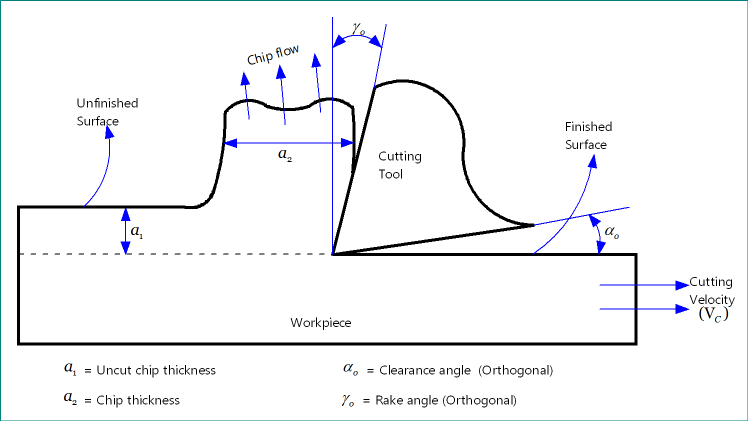
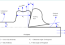
Rake surface is the chip flowing surface. Chips, which are produced during machining, continuously flow over the rake surface before leaving the cutting zone. Thus severe rubbing takes place between the chip face and rake face and as a result intense heat generates in that zone (called secondary deformation zone). Its inclination from reference plane, measured by rake angle, is influences many relevant parameters like shear deformation, chip thickness, cutting force, power consumption, etc. Apart from rake surface, every cutting tool should have at least one flank surface. Intersection of rake surface and flank surface produces cutting edge. Unlike rake surface, which remains in intimate contact with the flowing chips, flank surface remains open in adjacent with finished surface. However, due to presence of nose radius and edge radius, a tiny contact between machined surface and flank surface may occur. Various differences between rake surface and flank surface of a cutting tool are given below in table format.
Table: Differences between rake surface and flank surface
| Rake Surface | Flank Surface |
|---|---|
| During machining, chips flow over the rake surface. | Flank surface is not associated with chips. It touches the machined surface in a tiny portion. |
| Inclination of rake face is measured by rake angle. | Inclination of flank face is measured by clearance angle. |
| Major portion of rake surface remains in close contact with chip during machining. | Flank surface continuously remains free during operation. |
| Rake surface has no direct role in improving surface finish. | A tiny contact at tip of flank surface directly helps in improving finish by compressing scallop marks. |
| Intense heat generation occurs surrounding rake surface due to rubbing with flowing chips. | Insignificant amount of heat generates because of tiny contact at tip. |
| Due to excessive rubbing, rake surface quickly worn out (crater wear); however smaller wear does not hamper machining accuracy. | Although flank surface worn out slowly, but it directly influence dimensional accuracy of machined component. |
Contact with chip or finished surface: Rake surface remains in physical contact with the flowing chips during machining; however, it does not touch the finished or machined surface. On the other hand, chip does not touch the flank surface but finished surface touches the flank surface in a tiny portion due to presence of nose radius and edge radius. Such contact helps in smoothening scallop or feed marks; however, longer contact between machined surface and flank surface can hamper finishing quality. Thus sufficient gap (provided by clearance angle) has to be maintained mandatorily in between them to avoid rubbing.
Rake angle and clearance angle: These indicate inclination of tool point surfaces from standard plane or direction. By definition, rake angle is the angle of inclination of cutter’s rake surface from reference plane and measured on some other plane. Reference plane is a plane which is perpendicular to cutting velocity vector. On the basis of orientation of rake surface with respect to reference plane, rake angle may be wither positive, or negative or zero. Similarly, clearance angle is the measure of cutter’s flank surface from cutting velocity vector and measured on some other plane. However, clearance angle cannot be zero or negative, it must have a positive value. In both the cases, angle value may be different based on the plane on which it is measured.
Flank face remains exposed: As mentioned earlier, chips flow over the rake surface and thus it remains in close contact with flowing chips. However, flank surface always remain open as it neither touches chip nor touches finished surface (except a tiny portion at tip). However, flank surface may touch machined surface if cutter has worn out (flank wear), and in such scenario quality of machined surface will degrade steeply because of rubbing.
Flattening the feed marks: Scallop marks, which develops on finished surface due to presence of feed velocity, increase surface roughness and subsequently reduce finishing quality. Higher feed rate results rough surface; however, feed cannot be made zero because it is one of the two formative motions (other one being cutting velocity) indispensably necessary for every machining operation. A tiny contact between the flank surface and finished surface at tool tip due to presence of nose radius and edge radius inherently help in smoothening the surface by compressing scallop marks. Higher is the nose radius, better will be surface finish (i.e., low height of scallop marks); however, it may adversely impact other parameters. Rake surface has no direct role in improving surface finish.
Heat generation: As chips flow over rake surface, intense heat generation occurs due to rubbing. About 60 – 70% of total cutting heat arises due to this rubbing at secondary deformation zone. However, majority of generated heat is carried away from cutting zone by the moving chip. This protects the cutter as well as workpiece from overheating and other thermal damages. Contrary to this, only a fraction (below 5%) of total cutting heat generates due to tiny contact at tip. However, this heat partially flows inside the workpiece via finished surface and rest flows into cutter. Thus heat generated at tertiary rubbing zone can lead to thermal damages it exceeds certain limit.
Wear and its impact: Continuous rubbing accelerates abrasive wear rate of rake surface and thus crater wear occurs quickly. Although it changes chip flow direction and influences cutting force and other relevant parameters, a small crater wear is tolerable. However, flank wear directly influence accuracy of machined component and a tiny amount of wear can also lead to inaccuracy machining. Thus cutter life is conventionally determined by the allowable limit of flank wear (commonly it is limited to 0.3mm as per Taylor’s tool life formula).
Scientific comparison among rake surface and flank surface is presented in this article. The author also suggests you to go through the following references for better understanding of the topic.
- Machining and Machine Tools by A. B. Chattopadhyay (1st edition, Wiley).
- What is Clearance Angle in Cutting Tool? Its Derivative, Value and Function by minaprem.com.
- Image source: minaprem.com.