Machining or metal cutting is one subtractive manufacturing process where excess material is gradually removed in the form of chips from preformed blank using a cutting tool in order to impart intended shape, size and surface finish. To continuously remove (shear off) layers of material, a sharp edged cutter is indispensably necessary. During machining, relative motions are provided between workpiece and cutting tool in particular directions based on geometry of intended feature and selected operation. So cutter compresses a thin layer of material by its tip and subsequently shears it off. Since entire material shearing action is realized by this cutter, so its geometry, orientation and material are three crucial factors that influence entire machining performance.
What comes under cutter geometry?
Tool geometry deals with various geometrical features of the cutting tool that directly influence machining capability and performance. There exist a basic shape of cutter for every machining operations; however, many geometrical features may vary within certain limit to provide optimum result under specified conditions maintaining basic shape unaltered. Such features are also displayed in a standardized manner in various tool designation systems (for example, ASA, ORS, NRS, MRS, etc.).
Rake surface and flank surface are two important surfaces of every cutter and their inclinations are indicated with the help of rake angle and clearance angle, respectively. Certain cutters may also have more than one flank surface and accordingly they are named as primary and auxiliary flank surfaces and corresponding angle as primary and auxiliary clearance angles. A particular cutter may have varying angles based on the direction (or plane) it is measured and the same is also reflected in tool signatures (for example, side rake and back rake—both indicate inclination of rake surface but in different directions).
Apart from rake and clearance angles, tool signature may also display other information like nose radius. However, tool geometry may embrace other relevant information apart from those found in tool signature. Edge radius is one vital example.
Concept of edge and nose of cutter
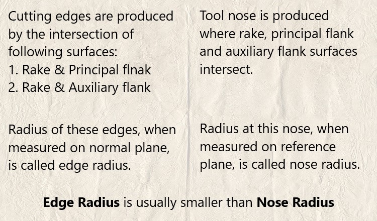
Physically edge occurs when two solid surfaces intersect and a nose occurs when three or more solid surfaces intersect together. In cutter also, edge emerges where rake surface and flank surface intersect and the same is termed as cutting edge. If cutter contains two flank surfaces, two cutting edges will be produced—primary cutting edge (intersection between rake surface and principal flank surface) and auxiliary cutting edge (intersection between rake surface and auxiliary flank surface). A cutter may contain one or more cutting edges and accordingly cutters can be classified as single point and multi-point cutting tool.
When three tool point surfaces (rake, principal flank and auxiliary flank) intersect together, a cutter nose emerges. During machining, this nose remains in physical contact with the workpiece and is subjected to extreme pressure and rubbing.
What is edge radius?
No edge is perfectly sharp. Even it is perfectly sharp, it cannot be measured accurately as every measuring instrument has limited capability. In fact, sharpness cannot be measured directly. It is the edge roundness that is measured and sharpness is inversely proportional to roundness. Higher the roundness or radius of the edge, less sharp it is. So roundness is quantitative measurement of edge radius; while, sharpness is qualitative measurement based on roundness value.
Value of edge radius: Although theoretical minimum limit for roundness is radius of the atom of concerned material, practically such an edge will have very low strength and thus has no application. This indicates a very sharp cutting edge (very low radius) will have low strength and thus will break quickly during machining. Thus a suitable roundness is provided at every edge of the cutter so that is does not fail or become dull quickly. Edge radius value usually varies in between 0.5 – 10µm for micro and precision tools and 10 – 500µm for conventional tools.
Effects of edge radius on macro-machining: In conventional macro-scale machining like turning, milling, drilling, etc., this parameter has insignificant influence on overall machining performance as uncut chip thickness is overwhelmingly larger than edge radius. Typically uncut chip thickness is 0.2 – 2mm, while edge radius is 0.5 – 10µm; that means 500 – 1000 times larger. Since it is trivial parameter in conventional machining, so it is not incorporated within tool signature of the corresponding cutter.
Effects of edge radius on micro-machining: However, when machining is carried out in micro or nano scale then edge radius becomes one predominant parameter that influence cutting capability and quality of machined surface. In such cases, edge radius becomes comparable with uncut chip thickness. For example, in micro-milling cutters (micro end mill), edge radius is typically 2 – 5µm, whereas feed rate (equivalent to uncut chip thickness in end milling) is only 0.5 – 10µm/flute. Similarly, in diamond turning (precision machining) edge radius is one significant parameter. Various investigations have revealed that minimum depth of cut has to be within 10 – 50% (based on other parameters) of the edge radius in order to efficiently remove material in every pass.
What is nose radius?
In cutting tool, nose is the result of intersection of rake surface, principal flank surface and auxiliary flank surface. As usual it cannot be perfectly sharp and one suitable roundness is provided on the tool tip. Radius of this rounded nose, when measured on reference plane, gives the value for nose radius. It is one significant parameter for conventional machining also as its value is close to uncut chip thickness.
Value of nose radius: Typically nose radius of conventional cutters varies between 0.8 – 2mm; whereas uncut chip thickness can be 0.2 – 2mm. For micro-cutters, nose radius is much smaller, typically few tens of microns.
Scientific comparison among edge radius and nose radius is presented in this article. In a conclusion it can be said that radius provided on the cutting edge is basically edge radius and the radius provided on tool tip is termed as nose radius. In conventional macro-scale machining, edge radius has insignificant influence but in micro-scale or precision machining it is one domination parameter. Nose radius, however, always influences machining performance.