Machining or metal cutting is one type of subtractive manufacturing process where excess material is gradually removed from the preformed blank to produce desired three dimensional feature or product. Conventional machining processes (like straight turning, taper turning, internal turning, threading, facing, drilling, boring, reaming, tapping, planing, shaping, slotting, milling, fly cutting, hobbing, grooving, parting, etc.) utilize a sharp wedge shaped cutting tool (cutter) to remove unwanted material. This cutter compresses a thin layer of work material and subsequently shears it off in the form of chips. Different processes utilize cutters having different shape; however, all of them encompass certain basic features for efficiently and productively removing material.
Material, orientation and geometry are three crucial parameters that influence machining performance and capability. A compatible cutter material should be selected based on work material and machining operation. Cutter should also be mounted on machine tool in proper orientation to continue machining uninterruptedly for longer duration. Cutter geometry refers to various angles and radius associated with cutting tool. It includes, but is not limited to, rake angles, clearance angles, cutting angles, nose radius, and edge radius. All these features, directly or indirectly, influence various machining characteristics in different scales. Some of these features are also displayed in the tool signature in a standardized manner.
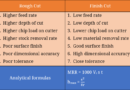
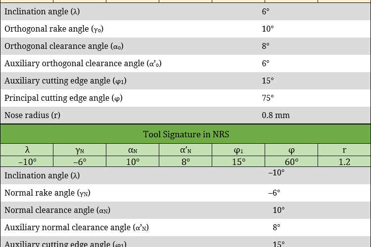
There exist quite a few tool designation systems—each of them independently displays corresponding tool signature. American Standards Association (ASA) system, Orthogonal Rake System (ORS), Normal Rake System (NRS), and Maximum Rake System (MRS) are commonly used single point turning tool (SPTT) designation systems. Different tool designation systems utilize different imaginary planes for reference purpose. ORS system of tool designation displays inclination angle, orthogonal rake angle, orthogonal clearance angle, auxiliary orthogonal clearance angle, auxiliary cutting edge angle, principal cutting edge angle, and nose radius. NRS system of tool designation displays inclination angle, normal rake angle, normal clearance angle, auxiliary normal clearance angle, auxiliary cutting edge angle, principal cutting edge angle, and nose radius. Various differences between ORS system and NRS system are given below in table format.
Table: Differences between ORS system and NRS system
| ORS system | NRS system |
|---|---|
| Full form of ORS is Orthogonal Rake System. | Full form of NRS is Normal Rake System. |
| It utilizes three imaginary planes for references. These are—reference plane, orthogonal plane, and cutting plane. | It also utilizes three imaginary planes for references. These are—reference plane, normal plane, and cutting plane. |
| Three imaginary planes are always mutually perpendicular to each other. | Three imaginary planes are not mutually perpendicular unless cutter has zero inclination angle. |
| Orthogonal rake angle is displayed in ORS system of tool designation. | Normal rake angle is displayed in NRS system of tool designation. |
| Usage of ORS system for tool grinding or sharpening using 3-D vice leads to error in setting angles. | NRS system eliminates error and additional calculation for obtaining correct setting angle in tool grinding. |
| ORS system is also known as ISO old system. | NRS system was adopted by replacing ORS system. So NRS is also called ISO new system. |
Full form of abbreviations: There are several cutting tool designation systems readily available and also commonly used. ASA, ORS and NRS are popular among them. ORS is the abbreviated form of Orthogonal Rake System. It is also frequently termed as Orthogonal Reference System. Both are correct. Similarly NRS is the abbreviated form of Normal Rake System or Normal Reference System.
Imaginary planes for referencing: Every tool designation system employs few imaginary flat planes in different directions and orientations. Various features of the cutting tool including angles and radius are measured with respect to these standard planes in order to maintain uniformity. ORS system employs three planes namely Reference Plane (PR), Orthogonal Plane (PO), and Cutting Plane (PC). NRS system also employs three plain planes namely Reference Plane (PR), Normal Plane (PN), and Cutting Plane (PC). Thus normal plane is used in NRS in place of orthogonal plane of ORS; the other two planes remain same in both the cases.
Relative positions of imaginary planes: Reference plane (PR) is a plane perpendicular to cutting velocity vector (Vc). Cutting plane (PC) is one plane that contains principal cutting edge of the cutter and is perpendicular to reference plane (PR). Orthogonal plane (PO) is oriented in third perpendicular direction and thus it is perpendicular to both reference plane and cutting plane. That means three imaginary planes of ORS system are always mutually perpendicular. This is not the case for NRS. The normal plane (PN) is perpendicular to principal cutting edge of the cutter. So if the principal cutting edge is not parallel to reference plane then normal plane will not be perpendicular to reference plane. The angle between principal cutting edge and reference plane (when measured on cutting plane) is called inclination angle (λ). Thus the angle between orthogonal plane and normal plane is also inclination angle. Therefore, three planes of NRS system are not mutually perpendicular unless inclination angle becomes zero. In such case (with λ=0°), NRS system and ORS system will be exactly same.
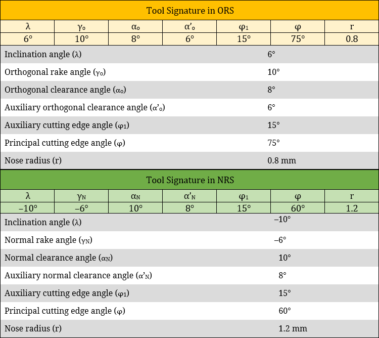
Orthogonal rake and normal rake: Rake angle is defined as the angle of inclination of the tools rake surface from reference plane and measured on some other plane. When it is measured by projecting on orthogonal plane, it is termed as orthogonal rake angle and the same is displayed in ORS tool designation system. Similarly when the angle is measured by projecting on normal plane, it is termed as normal rake angle and the same is displayed in NRS tool designation system. These two angles are widely used for various analysis relevant to machining and its performance.
Tool sharpening by grinding: Every cutter undergoes gradual wear during machining. Wear makes the cutting edges blunt (less sharp), which leads to undesirable increase in cutting force and surface roughness. Uncoated cutting tools can be sharpened by grinding in a regular interval to improve sharpness (reducing edge roundness). Single point turning tool can be ground by mounting it on a 3-D vice in proper fashion. It requires setting up multiple angles for each face of cutter. Such setting angles are calculated from the known tool signature. Use of ORS system for this calculation purpose leads to error; and thus requires additional calculations for compensation. Such limitation can be eliminated by employing features of NRS system during tool setting on 3-D vice. It is worth mentioning that use of MRS system for this purpose is best as it requires only two angle settings for each face; instead of 3 as in case of other systems.
ISO system: Earlier ORS system was international standard for turning tool designation. However, this system cannot reveal true picture of cutting tool. Now NRS system is overwhelmingly accepted international standard for turning tool designation.
Scientific comparison among ORS system and NRS system of turning tool is presented in this article. The author also suggests you to go through the following references for better understanding of the topic.
- Machining and Machine Tools by A. B. Chattopadhyay (1st edition, Wiley).
- Manufacturing Engineering and Technology: SI Edition by S. Kalpakjian and S. R. Schmid (7th edition, Pearson Ed Asia).